Micrium uCOS-II ARM Port
Introduction
uC/OSII has been running on ARM based processors since 1995 (in fact C/OS V1.x has).
There has been a number of ARM ports posted on the Micrium web site. The differences
have mostly to do with differences in compilers and what target board they run on.
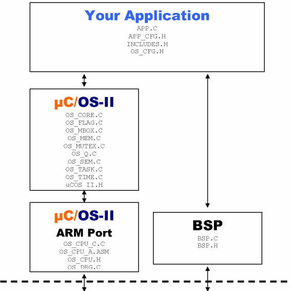
This application note describes the official’ Micrium port for uC/OSII. Figure 11
shows a block diagram showing the relationship between your application, uC/OSII,
the port code and the BSP (Board Support Package). Relevant sections of this application
note are referenced on the figure.
Note that the port described in this application note applies to both ARM7 and ARM9
processors and you can use this port for both ARM and Thumbbased applications. Previous
ports either worked in ARMmode or in Thumbmode. This port handles both.
Relationship between modules.
The ARM programmer’s model
Some of the most popular variant of the ARM processors are the ARM7TDMI and ARM92xT. The four letters stand for:
T (Thumb)
The T stands for Thumb instruction set which addresses the issue of code density. Specifically, Thumb mode allows instructions to be 16bits instead of 32bits thus reducing code density. A processor having the T suffix can thus run Thumb code.
D (Debug)
The D stands for debug support. This means that the specific ARM7 you are using offers onchip debug support, generally through a JTag interface.
M (Multiply)
The M means that the CPU contains a hardware multiply instruction.
I (EmbeddedICE macrocell)
Is the debug hardware built into the processor that allows breakpoints and watchpoints to be set.
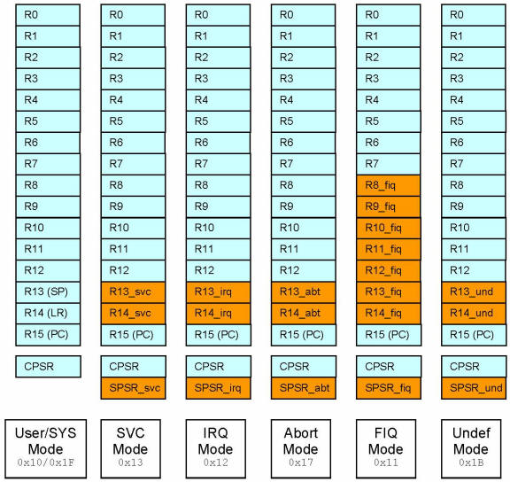
ARM Register Model
The visible registers in an ARM processor are shown in Figure 21. The ARM has a total of 37 registers. Each register is 32 bits wide. At any time, only 18 of those registers are directly visible’ by the processor: R0 through R15, CPSR and SPSR (SPSR is not visible in SYS mode).
R0-R12
R0 through R12 are general purpose registers that can be used to hold data as well as pointers.
R13
Is generally designated as the stack pointer (also called the SP) but could be the recipient of arithmetic operations.
R14
Is called the Link Register (LR) and is used to store the contents of the PC when a Branch and Link (BL) instruction is executed. The LR allows you to return to the caller.
The LR is also used during exception processing to store the contents of the PC prior to the exception.
R15
Is dedicated to be used as the Program Counter (PC) and points to the current instruction being executed.
As instructions are executed, the PC is incremented by either 2 (Thumb mode) or 4 (ARM mode).
The CPSR Register
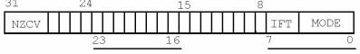
CPSR
- The CPSR (Current Processor Status Register) is used to store the condition code bits.
- These bits are used, for example, to record the result of a comparison
operation and to control whether or not a conditional branch is taken.
- Flags Status eXtension Control f’ s’ x’ c’
- The bottom 5 bits of the register control the processor mode.
| Bit |
Description |
|---|
| T |
Bit 5 determines whether the processor is executing Thumb (T == 1) or ARM code (T == 0). |
| F |
Bit 6 is the FIQ (Fast Interrupt Request) interrupt enable flag. Interrupts are recognized on the FIQ input of the processor when this bit is 0. Interrupts are disabled when it’s a 1. |
| I |
Bit 7 is the IRQ (Interrupt Request) interrupt enable flag. Interrupts are recognized when the bit is 0 and ignored when it’s a 1. |
| N |
Bit 31 is the negative’ bit and is set when the last ALU operation produced a negative result (i.e. the top bit of a 32bit result was a one). |
| Z |
Bit 30 is the zero’ bit and is set when the last ALU operation produced a zero result (every bit of the 32bit result was zero). |
| C |
Bit 29 is the carry’ bit and is set when the last ALU operation generated a carryout, either as a result of an arithmetic operation in the ALU or from the shifter. |
| V |
Bit 28 is the overflow’ bit and is set when the last arithmetic ALU operation generated an overflow into the sign bit. |
CPU Modes
The CPU can be in any of 7 modes: USER, SYS, SVC, IRQ, FIQ, ABORT and UNDEF.
| Mode |
Description |
| USER |
- The USER mode is the least privileged mode.
- Certain instructions cannot be executed when in this mode.
- For this reason, µC/OSII applications will never be in this mode.
- Only registers R0R15 and CPSR are visible by the processor in this mode.
|
| SYS |
- The SYS mode uses the same registers as in USER mode.
- SYS mode has all the privileges of the other modes.
- Only registers R0R15 and CPSR are visible’ by the processor in this mode.
|
| SVC |
- The SVC (Supervisor) mode is the default mode at power up.
- The processor can execute any instruction in this mode.
- R13_svc and R14_svc are visible instead of R13 and R14.
- The µC/OSII port runs in SVC mode.
|
| IRQ |
- When the Ibit of the CPSR is 0, the CPU will recognize interrupt requests
from the IRQ input of the processor.
- Registers R0-R12 are the same as SYS mode.
- It has its own R13_irq (the SP), R14_irq (the LR) and SPSR_irq registers.
- When an interrupt occurs, the CPU does the following:
- Switches mode to IRQ mode (MODE = 0x12)
- Saves the CPSR into the SPSR_irq register.
- Saves the PC into R14_irq (i.e. the Link Register of the IRQ mode)
- The Ibit of the CPSR is set to 1 disabling further IRQs.
- The PC is forced to address 0x00000018
|
| FIQ |
- When the Fbit of the CPSR is 0, the CPU will recognize interrupt requests
from the FIQ input of the processor.
- Registers R0-R7 are the same as SYS mode
- The FIQ mode has its own set of R8_fiq to R12_fiq and R13_fiq (the SP),
R14_fiq (the LR) and SPSR_fiq registers.
- When an interrupt occurs, the CPU does the following:
* Switches mode to FIQ mode (MODE = 0x11)
* Saves the CPSR into the SPSR_fiq register
* Saves the PC into R14_fiq (i.e. the Link Register of the FIQ mode)
* The Fbit and the Ibit of the CPSR are both set to 1 disabling further FIQs and IRQs
* The PC is forced to address 0x0000001C
|
| ABORT |
A memory abort is signaled by the memory system. Activating an abort in response
to an instruction fetch marks the fetched instruction as invalid. An abort will
take place if the processor attempts to execute the invalid instruction.
- Switches mode to ABORT mode (MODE = 0x17)
- Saves the CPSR into the SPSR_abt register
- Saves the PC into R14_abt (i.e. the Link Register of the ABORT mode)
- The Ibit of the CPSR is set to disable IRQs
- The PC is forced to address 0x0000000C
Activating an abort in response to a data access (Load or Store) marks the
data as invalid. A data abort will result in the following actions:
- Switches mode to ABORT mode (MODE = 0x17)
- Saves the CPSR into the SPSR_abt register
- Saves the PC into R14_abt (i.e. the Link Register of the ABORT mode)
- The I bit of the CPSR is set to disable IRQs
- The PC is forced to address 0x00000010
|
| UNDEF |
If ARM executes a coprocessor instruction, it waits for any external coprocessor
to acknowledge that it can execute the instruction. If no coprocessor responds,
an undefined instruction exception occurs.
- Switches mode to UNDEF mode (MODE = 0x1B)
- Saves the CPSR into the SPSR_und register
- Saves the PC into R14_und (i.e. the Link Register of the UNDEF mode)
- The Ibit of the CPSR is set to disable IRQs
- The PC is forced to address 0x00000004
|
Port for ARM Processors
IMPORTANT
The IAR compiler version that we used assumed that application code was running in SYS mode. In fact, the compiler calls main() in SYS mode. However, when we start uC/OSII, we switch the mode to SVC
Below are a few assumptions about the port:
- You have uC/OSII V2.77 or higher
- uC/OSII runs in either ARM mode or Thumb mode
- Tasks are created in the same mode as the one selected for running uC/OSII
- Tasks can call either ARM or Thumb mode functions
- Tasks will run in SVC mode
You can build the example code using either ARM (see figure 31) or Thumb (see
figure 32) mode. Note that you need to enable Generate interwork code.
Directories and Files
The software that accompanies this application note is assumed to be placed
in the following directory:
\Micrium\Software\uCOSII\ARM\Generic\IAR
Like all uC/OSII ports, the source code for the port is found in the following files:
- OS_CPU.H
- OS_CPU_C.C
- OS_CPU_A.ASM
- OS_DBG.C
Test code and configuration files are found in their appropriate directories and are described later.
OS_CPU.H
OS_CPU.H contains processorand implementationspecific #defines constants, macros, and typedefs.
macros for externals’
OS_CPU_GLOBALS and OS_CPU_EXT allows us to declare global variables that are specific to this port (described later).
Listing 31, OS_CPU.H, Globals and Externs
#ifdef OS_CPU_GLOBALS
#define OS_CPU_EXT
#else
#define OS_CPU_EXT extern
#endif
Data Types
Listing 32, OS_CPU.H, Data Types
typedef unsigned char BOOLEAN;
typedef unsigned char INT8U;
typedef signed char INT8S;
typedef unsigned short INT16U;        // (1)
typedef signed short INT16S;
typedef unsigned int INT32U;
typedef signed int INT32S;
typedef float FP32;                 // (2) typedef double FP64;

typedef unsigned int OS_STK;        // (3)
typedef unsigned int OS_CPU_SR;     // (4)
A short is 16 bits and an int is 32 bits. Most ARM compilers should have the same definitions.
Floating point data types are included even though uC/OSII doesn’t make use of floatingpoint numbers.
Since a stack entry for the ARM processor is always 32 bits wide, OS_STK is declared accordingly. All task stacks must be declared using OS_STK as its data type.
The status register (the CPSR and SPSR) on the ARM processor is 32 bits wide. The OS_CPU_SR data type is used when OS_CRITICAL_METHOD #3 is used (described below). In fact, this port only supports OS_CRITICAL_METHOD #3 because it’s the
preferred method for uC/OSII ports.
Critical Sections
uC/OSII, as with all realtime kernels, needs to disable interrupts in order to access
critical sections of code and reenable interrupts when done.
uC/OSII defines two macros to disable and enable interrupts: OS_ENTER_CRITICAL() and
OS_EXIT_CRITICAL(), respectively. uC/OSII defines three ways to disable interrupts but,
you only need to use one of the three methods for disabling and enabling interrupts.
The book (MicrouC/OSII, The RealTime Kernel) describes the three different methods. The one
to choose depends on the processor and compiler. In most cases, the prefered method
is OS_CRITICAL_METHOD #3.
OS_CRITICAL_METHOD #3 implements OS_ENTER_CRITICAL() by writing a function that will save
the status register of the CPU in a variable. OS_EXIT_CRITICAL() invokes another function
to restore the status register from the variable.
It’s recommended you call the functions expected in OS_ENTER_CRITICAL() and OS_EXIT_CRITICAL():
OS_CPU_SR_Save() and OS_CPU_SR_Restore(), respectively.
OS_CPU.H, OS_ENTER_CRITICAL() and OS_EXIT_CRITICAL()
#define OS_CRITICAL_METHOD 3
#if OS_CRITICAL_METHOD == 3
#if OS_CPU_INT_DIS_MEAS_EN > 0

#define OS_ENTER_CRITICAL() {cpu_sr = OS_CPU_SR_Save(); \
                             OS_CPU_IntDisMeasStart();}

#define OS_EXIT_CRITICAL() {OS_CPU_IntDisMeasStop(); \
                            OS_CPU_SR_Restore(cpu_sr);}
#else
#define OS_ENTER_CRITICAL() {cpu_sr = OS_CPU_SR_Save();}
#define OS_EXIT_CRITICAL() {OS_CPU_SR_Restore(cpu_sr);}
#endif
#endif
Stack growth
The stack on the ARM grows from high memory to low memory.
OS_STK_GROWTH is set to 1 to indicate this to uC/OSII.
- ::
- #define OS_STK_GROWTH 1
Task Level Context Switch
- Task level context switches are performed when uC/OSII invokes the macro OS_TASK_SW().
- OS_TASK_SW() needs to execute an assembly language function.
- OSCtxSw() which is declared in OS_CPU_A.ASM
Task Level Context Switch:
#define OS_TASK_SW() OSCtxSw()
Interrupt Control Function Prototypes
- Prototypes for the functions used to disable and reenable interrupts using OS_CRITICAL_METHOD #3
- These functions run in ARM mode.
#if OS_CRITICAL_METHOD == 3
__arm OS_CPU_SR OS_CPU_SR_Save(void);
__arm void OS_CPU_SR_Restore(OS_CPU_SR cpu_sr);
#endif
Exception Handling Functions
- OS_CPU_InitExceptVect() must be called from the BSP to initialize the CPU
exception vectors to the eight exception handlers.
- These eight exception handlers are the OS_CPU_ARM_XYZ assembly functions.
- These handlers save the CPU state and branch immediately to a common exception
handler, OS_CPU_ARM_ExceptHndlr().
- The common exception handler will do uC/OSII internal task management (save state, etc)
and will eventually call a board and application dependant exception handler,
OS_CPU_ExceptHndlr(), located in BSP.
- The __arm keyword indicates that these function will execute in ARM mode whether
called from Thumb or ARM mode code.
void OS_CPU_InitExceptVect(void);
__arm void OS_CPU_ARM_ExceptResetHndlr(void);
__arm void OS_CPU_ARM_ExceptUndefInstrHndlr(void);
__arm void OS_CPU_ARM_ExceptSwiHndlr(void);
__arm void OS_CPU_ARM_ExceptPrefetchAbortHndlr(void);
__arm void OS_CPU_ARM_ExceptDataAbortHndlr(void);
__arm void OS_CPU_ARM_ExceptAddrAbortHndlr(void);
__arm void OS_CPU_ARM_ExceptIrqHndlr(void);
__arm void OS_CPU_ARM_ExceptFiqHndlr(void);
void OS_CPU_ExceptHndlr(INT32U except_type);
Context Switch Functions
- The prototypes for OSCtxSw(), OSIntCtxSw() and OSStartHighRdy() need to be placed in OS_CPU.H.
- It makes sense to do this since these are all port specific files.
- ::
- __arm void OSCtxSw(void);
__arm void OSIntCtxSw(void);
__arm void OSStartHighRdy(void);
Interrupt disable time measuring Functions
- Read the value of a timer just after disabling interrupts and read it again before enabling interrupts.
- The difference in timer counts indicates the amount of time interrupts were disabled.
- OS_CPU_IntDisMeasStop() keeps track of the highest value of this delta counts and
the maximum interrupt disable time.
#if OS_CRITICAL_METHOD == 3
void OS_CPU_IntDisMeasInit(void);
void OS_CPU_IntDisMeasStart(void);
void OS_CPU_IntDisMeasStop(void);
INT16U OS_CPU_IntDisMeasTmrRd(void);
#endif
OS_CPU_C.C
A full uC/OSII port requires that you write ten fairly simple C functions:
* OSInitHookBegin()
* OSInitHookEnd()
* OSTaskCreateHook()
* OSTaskDelHook()
* OSTaskIdleHook()
* OSTaskStatHook()
* OSTaskStkInit()
* OSTaskSwHook()
* OSTCBInitHook()
* OSTimeTickHook()
Typically, uC/OSII only requires OSTaskStkInit(). The other functions allow you to
extend the functionality of the OS with your own functions.
The following functions have been added in order to measure interrupt disable
time:
- OS_CPU_IntDisMeasInit()
- OS_CPU_IntDisMeasStart()
- OS_CPU_IntDisMeasStop()
Note that you will also need to set the #define constant OS_CPU_HOOKS_EN to 1 in OS_CFG.H
in order for the compiler to use the functions declared in this file.
OSInitHookBegin()
This function is called by uC/OSII’s OSInit() at the very beginning of OSInit(). It gives
the opportunity to add additional initialization code specific to the port.
We initialize the global variable (global to OS_CPU_C.C) OSTmrCtr (which is
used by the OS_TMR.C module (if OS_TMR_EN is set to 1).
void OSInitHookBegin (void)
{
#if OS_TMR_EN > 0
    OSTmrCtr = 0;
#endif
}
OSInitHookEnd()
- This function is called by uC/OSII’s OSInit() at the very end of OSInit().
- It gives the opportunity to add additional initialization code specific to the port.
- In this case, we initialize global variables which are used by the interrupt disable
measurement code (if OS_CPU_INT_DIS_MEAS_EN is set to 1).
void SInitHookEnd (void)
{
#if OS_CPU_INT_DIS_MEAS_EN > 0
    OS_CPU_IntDisMeasInit();
#endif
}
OSTaskCreateHook()
This function is called by uC/OSII’s OSTaskCreate() or OSTaskCreateExt() when
a task is created. OSTaskCreateHook() gives the opportunity to add code specific
to the port when a task is created. In our case, we call the initialization function
of C/OSView (an optional module available for uC/OSII which performs task profiling
at runtime, See HTU www.micrium.comUTH for details).
Note that for OSView_TaskCreateHook() to be called, the target resident code for C/OSView
must be included as part of your build. In this case, you need to add a #define OS_VIEW_MODULE 1
in OS_CFG.H of your application.
Note that if OS_VIEW_MODULE is 0, we simply tell the compiler that ptcb is not actually
used (i.e. (void)ptcb)) and thus avoid a compiler warning.
void OSTaskCreateHook (OS_TCB *ptcb)
{
#if OS_VIEW_MODULE > 0
    OSView_TaskCreateHook(ptcb);
#else
    (void)ptcb;
#endif
}
OSTaskStkInit()
uC/OSII assumes that tasks run in SVC mode (the CPSR of the task is
initialized to ARM_SVC_MODE (0x13 if in ARM mode or 0x33 if in Thumb mode).
It is typical for ARM compilers to pass the first argument of a function into
the R0 register. Recall that a task is declared as shown in listing 312.
void MyTask (void *p_arg)
{
    /* Do something with p_arg', optional */
    while (1)
    {
        /* Task body */
    }
}
The code below initializes the stack frame for the task being created. The task received
an optional argument p_arg’. That’s why p_arg’ is passed in R0 when the task is created.
The initial value of most of the CPU registers is not important so, we decided to initialize
them to values corresponding to their register number. This makes it convenient when debugging
and examining stacks in RAM.
The initial values are thus useful when the task is first created but, of course, the register
values will most likely change as the task code is executed.
OS_STK *OSTaskStkInit (void (*task)(void *pd), void *p_arg, OS_STK *ptos, INT16U opt)
{
    OS_STK *stk;
    INT32U task_addr;
    opt = opt;                                  /* 'opt' is not used, prevent warning */
    stk = ptos;                                 /* Load stack pointer */
    task_addr = (INT32U)task & ~1;
    *(stk) = (INT32U)task_addr;                 /* Entry Point */
    *(stk) = (INT32U)0x14141414L;                /* R14 (LR) */
    *(stk) = (INT32U)0x12121212L;               /* R12 */
    *(stk) = (INT32U)0x11111111L;               /* R11 */
    *(stk) = (INT32U)0x10101010L;               /* R10 */
    *(stk) = (INT32U)0x09090909L;               /* R9 */
    *(stk) = (INT32U)0x08080808L;               /* R8 */
    *(stk) = (INT32U)0x07070707L;               /* R7 */
    *(stk) = (INT32U)0x06060606L;               /* R6 */
    *(stk) = (INT32U)0x05050505L;               /* R5 */
    *(stk) = (INT32U)0x04040404L;               /* R4 */
    *(stk) = (INT32U)0x03030303L;               /* R3 */
    *(stk) = (INT32U)0x02020202L;               /* R2 */
    *(stk) = (INT32U)0x01010101L;               /* R1 */
    *(stk) = (INT32U)p_arg;                     /* R0 : argument */

    if ((INT32U)task & 0x01)
    {
                                                /* See if task runs in Thumb or ARM mode */
        *(stk) = (INT32U)ARM_SVC_MODE_THUMB;    /* CPSR THUMBmode) */
    }
    else
    {
        *(stk) = (INT32U)ARM_SVC_MODE_ARM;      /* CPSR ARMmode) */
    }
    return (stk);
}
The Stack Frame for each Task for ARM port.The figure shows how the stack frame is initialized for each task when it’s
created:
stk ------------------> CPSR = ARM_SVC_MODE_???         Low Memory
                        R0   = p_arg
                        R1   = 0x01010101
                        R2   = 0x02020202
                        R3   = 0x03030303
                        R4   = 0x04040404
                        R5   = 0x05050505
                        R6   = 0x06060606
                        R7   = 0x07070707
                        R8   = 0x08080808
                        R9   = 0x09090909
                        R10  = 0x10101010
                        R11  = 0x11111111
                        R12  = 0x12121212
                        LR   = 0x14141414
ptos -----------------> PC   = task                     Hig Memory
When the task is created, the final value of stk is placed in the OS_TCB of
that task by the uC/OSII function that calls OSTaskStkInit()
(i.e. OSTaskCreate() or OSTaskCreateExt()).
OSTaskSwHook()
- OSTaskSwHook() is called when a context switch occurs.
- This function allows the port code to be extended and do things
such as measuring the execution time of a task, output a pulse on
a port pin when a contact switch occurs, etc.
- In this case, we call the C/OSView task switch hook called OSView_TaskSwHook().
- This assumes that you have C/OSView as part of your build and that you set
OS_VIEW_MODULE to 1 in OS_CFG.H.
void OSTaskSwHook (void)
{
#i#if OS_VIEW_MODULE > 0
    OSView_TaskSwHook();
#dif
} }
OSTimeTickHook()
OSTimeTickHook() is called at the very beginning of OSTimeTick(). This function allows
the port code to be extended and, in our case, we call the C/OSView function OSView_TickHook().
Again, this assumes that you have C/OSView as part of your build and that you set
OS_VIEW_MODULE to 1 in OS_CFG.H.
OSTimeTickHook() also determines whether it’s time to update the uC/OSII timers. This is
done by signaling the timer task.
void OSTimeTickHook (void)
{
#if OS_VIEW_MODULE > 0
    OSView_TickHook();
#endif
#if OS_TMR_EN > 0
    OSTmrCtr++;
    if (OSTmrCtr >= (OS_TICKS_PER_SEC / OS_TMR_CFG_TICKS_PER_SEC))
    {
        OSTmrCtr = 0;
        OSTmrSignal();
    }
#endif
}
OS_CPU_IntDisMeasInit()
OS_CPU_IntDisMeasInit() is called by OSInitHookEnd() (see section 3.03.01) to initialize
the interrupt disable time measurement variables as shown below.
Basically, we added functions to the port to allow us to measure the amount of time that
interrupts are disabled. This is not something that is needed by the port but it can provide
valuable information about the responsiveness of your system to interrupts.
The way interrupt disable time measurement works is simple. Just after disabling interrupts,
we read the contents of a free running 16bit (or 32bit) timer. Just before reenabling interrupts,
we read the free running counter again and compute the difference between the two readings.
Maximum interrupt disable time is obtained by tracking the highest value of the difference.
The value of the difference represents timer counts and thus, to convert to actual time, you
need to know how fast the counter is being incremented (or decremented).
The function in listing 316 initializes the measurement and can actually be called at any time
to reset’ the maximum count.
#if OS_CPU_INT_DIS_MEAS_EN > 0 void OS_CPU_IntDisMeasInit (void)
{
    OS_CPU_IntDisMeasNestingCtr = 0;    /* Clear variables used by these functions */
    OS_CPU_IntDisMeasCntsEnter = 0;
    OS_CPU_IntDisMeasCntsExit = 0;
    OS_CPU_IntDisMeasCntsMax = 0;
    OS_CPU_IntDisMeasCntsDelta = 0;
    OS_CPU_IntDisMeasCntsOvrhd = 0;
    OS_CPU_IntDisMeasStart();           /* Measure the overhead of the functions */
    OS_CPU_IntDisMeasStop();
    OS_CPU_IntDisMeasCntsOvrhd = OS_CPU_IntDisMeasCntsDelta;
}
#endif
OS_CPU_IntDisMeasStart()
OS_CPU_IntDisMeasStart() is called when interrupts are disabled by OS_ENTER_CRITICAL().
#if OS_CPU_INT_DIS_MEAS_EN > 0
void OS_CPU_IntDisMeasStart (void)
{
    OS_CPU_IntDisMeasNestingCtr++;          // (1)
    if (OS_CPU_IntDisMeasNestingCtr == 1)   // (2)
    {
        OS_CPU_IntDisMeasCntsEnter = OS_CPU_IntDisMeasTmrRd();
    }
}
#endif
- A nesting counter is maintained in case you nest OS_ENTER_CRITICAL() calls.
- If this is the first level of nesting for OS_ENTER_CRITICAL() then, we call
a function that you would define in your application called OS_CPU_IntDisMeasTmrRd()
to read the value of a 16bit freerunning timer.
Note that you could also use a 32bit timer. In this case, you would simply redeclare
the variables and prototypes accordingly. The value of the timer is saved in OS_CPU_IntDisMeasCntsEnter.
OS_CPU_IntDisMeasStop()
OS_CPU_IntDisMeasStop() is called when interrupts are reenabled by OS_EXIT_CRITICAL().
#if  OS_CPU_INT_DIS_MEAS_EN  >  0
void  OS_CPU_IntDisMeasStop  (void)
{
    OS_CPU_IntDisMeasNestingCtr;                                            // (1)
    if  (OS_CPU_IntDisMeasNestingCtr  ==  0)
    {
        OS_CPU_IntDisMeasCntsExit  =  OS_CPU_IntDisMeasTmrRd();
        OS_CPU_IntDisMeasCntsDelta  =  OS_CPU_IntDisMeasCntsExit -          // (2)
                                       OS_CPU_IntDisMeasCntsEnter;

        if  (OS_CPU_IntDisMeasCntsDelta  >  OS_CPU_IntDisMeasCntsOvrhd)     // (3)
        {
            OS_CPU_IntDisMeasCntsDelta  =  OS_CPU_IntDisMeasCntsOvrhd;
        }
        else
        {
            OS_CPU_IntDisMeasCntsDelta  =  OS_CPU_IntDisMeasCntsOvrhd;
        }
        if  (OS_CPU_IntDisMeasCntsDelta  >  OS_CPU_IntDisMeasCntsMax)       // (4)
        {
            OS_CPU_IntDisMeasCntsMax  =  OS_CPU_IntDisMeasCntsDelta;
        }
    }
}
#endif
- The nesting counter is decremented so that we only take a time measurement at the
last nested OS_EXIT_CRITICAL() calls.
- We measure the difference in timer value since interrupts were disabled.
- We make sure that the counts are higher than the measured overhead so we don’t
subtract a number that is larger than the delta. This would cause a large’ count
for the measured interrupt disable time.
- We record the highest value in OS_CPU_IntDisMeasCntsMax.
OS_CPU_A.ASM
A uC/OSII port requires that you write five fairly simple assembly language functions.
The ARM port actually contains fourteen functions because portions of the exception
handling code are written in assembly language as discussed in this section.
These functions are needed because you normally cannot save/restore registers from C functions.
The fourteen functions are:
- OS_CPU_SR_Save()
- OS_CPU_SR_Restore()
- OSStartHighRdy()
- OSCtxSw()
- OSIntCtxSw()
- OS_CPU_InitExceptVect()
- OS_CPU_ARM_ExceptResetHndlr()
- OS_CPU_ARM_ExceptUndefInstrHndlr()
- OS_CPU_ARM_ExceptSwiHndlr()
- OS_CPU_ARM_ExceptPrefetchAbortHndlr()
- OS_CPU_ARM_ExceptDataAbortHndlr()
- OS_CPU_ARM_ExceptAddrAbortHndlr()
- OS_CPU_ARM_ExceptIrqHndlr()
- OS_CPU_ARM_ExceptFiqHndlr()
OS_CPU_SR_Save()
The code in listing 319 implements the saving of the CPSR register and then disabling
interrupts for OS_CRITICAL_METHOD #3. The code follows the application note published
by Atmel (Disabling Interrupts at Processor Level?) for properly disabling interrupts
on the ARM. In this implementation, both the FIQ and IRQ interrupts are disabled.
You should note that we use the BX LR instruction to return to the appropriate mode.
Specifically, if OS_CPU_SR_Save() was called from ARM mode code, CPSR bit 5 would stay at 0.
If we return to Thumb mode code then CPSR bit 5 will be set to 1 by the BX instruction.
When this function returns, R0 contains the state of the CPSR register prior to disabling interrupts.
OS_CPU_SR_Save:
    MRS R0, CPSR         ; Set IRQ and FIQ bits in CPSR to disable all interrupts.
    ORR R1, R0, #OS_CPU_ARM_CONTROL_INT_DIS
    MSR CPSR_c, R1
    BX LR                ; Disabled, return the original CPSR contents in R0.
OS_CPU_SR_Restore()
The code in the listing below implements the function to restore the CPSR register
for OS_CRITICAL_METHOD #3. When called, it’s assumed that R0 contains the desired
state of the CPSR register. You should note that we only update the control’ field of
the CPSR (i.e. lower 8 bits of the CPSR).
Again, the BX LR instruction returns to the appropriate mode (ARM or Thumb).
OS_CPU_SR_Restore:
    MSR CPSR_c, R0
    BX LR
OSStartHighRdy()
OSStartHighRdy() is called by OSStart() to start running the highest priority task
that was created before calling OSStart(). OSStart() sets OSTCBHighRdy to point to
the OS_TCB of the highest priority task.
OSStartHighRdy:
                                            ; (1) Change to SVC mode.
    MSR CPSR_c, #(OS_CPU_ARM_CONTROL_INT_DIS | OS_CPU_ARM_MODE_SVC)
    LDR R0, ?OS_TaskSwHook                  ; (2) OSTaskSwHook();
    MOV LR, PC BX R0
    LDR R0, ?OS_Running                     ; (3) OSRunning = TRUE;
    MOV R1, #1 STRB R1, [R0]                ; SWITCH TO HIGHEST PRIORITY TASK.
    LDR R0, ?OS_TCBHighRdy                  ; (4) Get highest priority task TCB address.
    LDR R0, [R0]                            ; get stack pointer.
    LDR SP, [R0]                            ; switch to the new stack.
    LDR R0, [SP], #4                        ; (5) Prepare to return to proper mode ¦ MSR SPSR_cxsf, R0 ¦ (ARM or Thumb)
    LDMFD SP!, {R0R12, LR, PC}^             ; (6) pop new task's context.
The IAR compiler startup code sets the mode to SYS mode prior to
calling main(). We decided to use SVC mode for the µC/OSII because it allows
us to use the SPSR register to return to the proper mode (ARM or Thumb) as
described in L321(7). Interrupts should not be enabled at this point but,
just to make sure, we disable them.
Before starting the highest priority task, we call OSTaskSwHook() in
case a hook call has been declared. Note that we use a BX instruction
because OSTaskSwHook() could be compiled in either ARM or Thumb mode. All
ARM instructions are all 32 bits and thus, the ARM is not able to specify a
32bit address as part of the instruction. Because of that, the address of
OSTaskSwHook() is actually declared at the end of the file and the ARM
obtains this address via a PCrelative address. Specifically:
?OS_TaskSwHook:
    DC32 OSTaskSwHook
DC32 is an assembler directive that declares storage for a 32 bit constant
that resides in code. ?OS_Running is thus just a local label.
The µC/OSII flag OSRunning is set to TRUE indicating that µC/OSII will
be running once the first task is started. All ARM instructions are all 32
bits and thus, the ARM is not able to specify a 32bit address as part of the
instruction. Because of that, the address of OSRunning is actually declared
at the end of the file and the ARM obtains this address via a PCrelative
address. Specifically:
?OS_Running:
    DC32 OSRunning
We then get the pointer to the task’s topofstack (was stored by
OSTaskCreate() or OSTaskCreateExt()). See figure 31 (stk is stored in the
OS_TCB of the created task).
We then pop the CPSR from the task’s stack but we place it in the SPSR
register. Recall that when the task was created, the CPSR register on the
stack frame was initialized with ARM_SVC_MODE_Mode (0x00000013 for ARM mode
or 0x00000033 for Thumb mode). The next instruction will restore the CPSR
register from the SPSR register and place the task in the proper mode (ARM
or Thumb) according to the value retrieved for the SPSR.
We then pop the remaining registers of the task’s context from the
stack. Because the PC is the last element popped off the stack, the CPU
immediately jumps to that address when it’s loaded. In other words, we will
run the beginning of the task code as soon as the PC is loaded. Note that
the ^’ indicates to also copy the SPSR to the CPSR register which places the
task in the proper mode (ARM or Thumb).
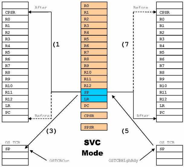
OSCtxSw()
The code to perform a task level’ context switch is shown below in pseudocode. OSCtxSw() is called when a higher priority task is made ready to run by
another task or, when the current task can no longer execute (e.g. it calls OSTimeDly(), OSSemPend() and the semaphore is not available, etc.).
Recall that all tasks run in SVC mode. A task level context switch simply consists
of saving the SVC registers on the task to suspend and restore the SVC registers of
the new task (see also Figure 32). The pseudo code for this is shown below:
SaSave the CPU registers onto the old task's stack;     /* (1) */
OSPrioCur = OSPrioHighRdy;                              /* (2) */
OSTCBCur>OSTCBStkPtr = SP;                           /* (3) */
OSTaskSwHook();                                         /* (4) */
SP = OSTCBHighRdy>OSTCBStkPtr;                       /* (5) */
OSTCBCur = OSTCBHighRdy;                                /* (6) */
Restore the CPU registers from the new task's stack;    /* (7) */
You will notice that we don’t actually save and restore the SPSR register as part of
a context switch. The reason is that the SPSR is only used to return to the appropriate
task and is always used with interrupts disabled.
Task Level Context Switch
The actual code for the task level context switch is shown below:
OSCtxSw                             ; SAVE CURRENT TASK'S CONTEXT
    STMFD SP!, {LR}                 ; Push return address
    STMFD SP!, {LR}
    STMFD SP!, {R0R12}              ; Push registers
    MRS R0, CPSR                    ; Push current CPSR
    TST LR, #1                      ; See if called from Thumb mode
    ORRNE R0, R0, #OS_CPU_ARM_CONTROL_THUMB     ; If yes, Set the Tbit
    STMFD SP!, {R0}

    LDR R0, ?OS_TCBCur              ; OSTCBCur>OSTCBStkPtr = SP;
    LDR R1, [R0]
    STR SP, [R1]

    LDR R0, ?OS_TaskSwHook          ; OSTaskSwHook();
    MOV LR, PC
    BX R0

    LDR R0, ?OS_PrioCur             ; OSPrioCur = OSPrioHighRdy;
    LDR R1, ?OS_PrioHighRdy
    LDRB R2, [R1]
    STRB R2, [R0]

    LDR R0, ?OS_TCBCur             ; OSTCBCur = OSTCBHighRdy;
    LDR R1, ?OS_TCBHighRdy
    LDR R2, [R1]
    STR R2, [R0]

    LDR SP, [R2]                    ; SP = OSTCBHighRdy>OSTCBStkPtr;
                                    ; RESTORE NEW TASK'S CONTEXT
    LDMFD SP!, {R0}                 ; Pop new task's CPSR
    MSR SPSR_cxsf, R0

    LDMFD SP!, {R0R12, LR, PC}^     ; Pop new task's context
OSIntCtxSw()
When an exception handler completes, OSIntExit() is called to determine whether
a more important task than the interrupted task needs to execute. If that’s the case,
OSIntExit() determines which task to run next and calls OSIntCtxSw() to perform
the actual context switch to that task. You will notice that OSIntCtxSw() is identical
to the second half of OSCtxSw().
The reason we have these as two separate functions is to simplify debugging. Specifically,
if you wanted to set a breakpoint in OSIntCtxSw(), you would hit the breakpoint during a
task level context switch (if OSIntCtxSw() was just a label in OSCtxSw()). Of course
this would make debugging a bit difficult.
OSIntCtxSw:
    LDR R0, ?OS_TaskSwHook         ; OSTaskSwHook();
    MOV LR, PC
    BX R0

    LDR R0, ?OS_PrioCur         ; OSPrioCur = OSPrioHighRdy;
    LDR R1, ?OS_PrioHighRdy
    LDRB R2, [R1]
    STRB R2, [R0]

    LDR R0, ?OS_TCBCur         ; OSTCBCur = OSTCBHighRdy;
    LDR R1, ?OS_TCBHighRdy
    LDR R2, [R1]
    STR R2, [R0]

    LDR SP, [R2]             ; SP = OSTCBHighRdy>OSTCBStkPtr;
                    ; RESTORE NEW TASK'S CONTEXT.
    LDMFD SP!, {R0}             ; Pop new task's CPSR.
    MSR SPSR_cxsf, R0

    LDMFD SP!, {R0R12, LR, PC}^     ; Pop new task's context.
Exception Handlers
The eight ARM exception handlers are part of the uC/OSII port to reduce the amount
of work needed by the programmer that’s integrating uC/OSII in his or her product.
InIn fact, the eight exception handlers are written in a generic way and can actually
be used by ANY ARM processor whether it has a builtin interrupt controller or not.
The CPU exception vectors are initialized by the OS_CPU_ARM_InitExceptVect() function.
This function maps the eight exception vectors to eight handlers, OS_CPU_ARM_Except_XYZ_Hndlr().
Listing below presents one of those handlers, OS_CPU_ARM_ExceptIrqHnldr().
The eight handlers all need to:
- Save registers R0 to R12, the LR (adjusted to compensate for the pipeline)
- Branch to a global handler called OS_CPU_ARM_ExceptHndlr().
OS_CPU_ARM_ExceptHndlr() determines if the exception interrupted a task or another
lower priority exception. It branches either to OS_CPU_ARM_ExceptHndlr_BreakTask()
or OS_CPU_ARM_ExceptHndlr_BreakExcept().
Both these branches eventually call a board and CPU dependent exception handler,
OS_CPU_ExceptHndlr(), located in the BSP (Board Support Package).
All these handlers (except OS_CPU_ExceptHndlr()) are written in assembly language
because we can’t manipulate CPU registers directly from C.
OS_CPU_ARM_ExceptIrqHndlr()
;**************************************************************************
; INTERRUPT REQUEST EXCEPTION HANDLER
;
; Register Usage: R0 Exception Type
; R1
; R2
; R3 Return PC
;**************************************************************************
OS_CPU_ARM_ExceptIrqHndlr:
SUB LR, LR, #4 ; LR offset to return from this exception: 4.
STMFD SP!, {R0R12, LR} ; Push working registers.
MOV R3, LR ; Save link register.
; Set exception ID to OS_CPU_ARM_EXCEPT_IRQ.
MOV R0, #OS_CPU_ARM_EXCEPT_IRQ
; Branch to global exception handler.
B OS_CPU_ARM_ExceptHndlr
OS_CPU_ARM_ExceptHndlr()
;**************************************************************************
; GLOBAL EXCEPTION HANDLER
;
; Register Usage: R0 Exception Type
; R1 Exception's SPSR
; R2 Old CPU mode
; R3 Return PC
;**************************************************************************

OS_CPU_ARM_ExceptHndlr:
    MRS R1, SPSR        ; Save CPSR (i.e. exception's SPSR).
                        ; DETERMINE IF WE INTERRUPTED A TASK
                        ; OR ANOTHER LOWER PRIORITY EXCEPTION.
                        ; SPSR.Mode = FIQ, IRQ, ABT, UND : Other exception
                        ; SPSR.Mode = SVC : Task ; SPSR.Mode = USR : *unsupported state*
    AND R2, R1, #OS_CPU_ARM_MODE_MASK
    CMP R2, #OS_CPU_ARM_MODE_SVC
    BNE OS_CPU_ARM_ExceptHndlr_BreakExcept
OS_CPU_ARM_ExceptHndlr_BreakTask()
;**************************************************************************
; EXCEPTION HANDLER: TASK INTERRUPTED
;
; Register Usage: R0 Exception Type
; R1 Exception's SPSR
; R2 Exception's CPSR
; R3 Return PC
; R4 Exception's SP
;**************************************************************************
OS_CPU_ARM_ExceptHndlr_BreakTask:
MRS R2, CPSR ; Save exception's CPSR.
MOV R4, SP ; Save exception's stack pointer.
; Change to SVC mode & disable interruptions.
MSR CPSR_c, #(OS_CPU_ARM_CONTROL_INT_DIS | OS_CPU_ARM_MODE_SVC)
; SAVE TASK'S CONTEXT ONTO TASK'S STACK.
STMFD SP!, {R3} ; Push task's PC.
STMFD SP!, {LR} ; Push task's LR.
STMFD SP!, {R5R12} ; Push task's R12R5.
LDMFD R4!, {R5R9} ; Move task's R4R0 from exception stack to task stack.
STMFD SP!, {R5R9}
STMFD SP!, {R1} ; Push task's CPSR (i.e. exception SPSR).
LDR R1, ?OS_Running ; if (OSRunning == 1)
LDRB R1, [R1]
CMP R1, #1
BNE OS_CPU_ARM_ExceptHndlr_BreakTask_1
; HANDLE NESTING COUNTER.
LDR R3, ?OS_IntNesting ; OSIntNesting++;
LDRB R4, [R3]
ADD R4, R4, #1
STRB R4, [R3]
LDR R3, ?OS_TCBCur ; OSTCBCur>OSTCBStkPtr = SP;
LDR R4, [R3]
STR SP, [R4]
OS_CPU_ARM_ExceptHndlr_BreakTask_1:
MSR CPSR_cxsf, R2 ; RESTORE INTERRUPTED MODE.
; EXECUTE EXCEPTION HANDLER:
; OS_CPU_ExceptHndlr();
LDR R1, ?OS_CPU_ExceptHndlr
MOV LR, PC
BX R1
; Adjust exception stack pointer. This is needed because
; exception stack is not used when restoring task context. ADD SP, SP, #(14*4)
; Change to SVC mode & disable interruptions.
MSR CPSR_c, #(OS_CPU_ARM_CONTROL_INT_DIS | OS_CPU_ARM_MODE_SVC)
; Call OSIntExit(). This call MAY never return
; if a ready task with higher priority than
; the interrupted one is found.
LDR R0, ?OS_IntExit
MOV LR, PC
BX R0
; RESTORE NEW TASK'S CONTEXT.
LDMFD SP!, {R0} ; Pop new task's CPSR.
MSR SPSR_cxsf, R0
LDMFD SP!, {R0R12, LR, PC}^ ; Pop new task's context.
OS_CPU_ARM_ExceptHndlr_BreakExcept()
;*************************************************************************
; EXCEPTION HANDLER: EXCEPTION INTERRUPTED
;
; Register Usage: R0 Exception Type
; R1
; R2
; R3
;*************************************************************************
OS_CPU_ARM_ExceptHndlr_BreakExcept:
MRS R2, CPSR ; Save exception's CPSR.
; Change to SVC mode & disable interruptions.
MSR CPSR_c, #(OS_CPU_ARM_CONTROL_INT_DIS | OS_CPU_ARM_MODE_SVC)
; HANDLE NESTING COUNTER.
LDR R3, ?OS_IntNesting ; OSIntNesting++;
LDRB R4, [R3]
ADD R4, R4, #1
STRB R4, [R3]
MSR CPSR_cxsf, R2 ; RESTORE INTERRUPTED MODE.
; EXECUTE EXCEPTION HANDLER:
; OS_CPU_ExceptHndlr();
LDR R3, ?OS_CPU_ExceptHndlr
MOV LR, PC
BX R3
; Change to SVC mode & disable interruptions.
MSR CPSR_c, #(OS_CPU_ARM_CONTROL_INT_DIS | OS_CPU_ARM_MODE_SVC)
; HANDLE NESTING COUNTER.
LDR R3, ?OS_IntNesting ; OSIntNesting;
LDRB R4, [R3]
SUB R4, R4, #1
STRB R4, [R3]
MSR CPSR_cxsf, R2 ; RESTORE INTERRUPTED MODE.
; RESTORE OLD CONTEXT:
LDMFD SP!, {R0R12, PC}^ ; Pull working registers and return from exception.
Note
MOST of the work done by the exception handler is actually handled
in OS_CPU_ExceptHndlr() (located in the BSP) which is written in C. The pseudocode
for OS_CPU_ExceptHndlr() is shown below.
The handler is responsible for discriminate exceptions and interruptions, determining the
source of the interruptions and for executing the appropriate code to handle the
interrupting device.
OS_CPU_ExceptHndlr()
void OS_CPU_ExceptHndlr (INT32U except_type)
{
    /* Determine behavior according to exception type (except_type) */
    /* If an IRQ or FIQ */
    while (there are interrupting devices)
    {
        /* Clear interrupting device */
        /* Handle interrupt */
    }
}
OS_CPU_ExceptHndlr() is actually part of YOUR application and not part of the uC/OSII port.
The reason is that the handler will most likely change depending on the presence of
an interrupt controller or not and, if there is an interrupt controller, the actual
type of controller.
It’s important to note that the handler should look to see whether there are more than
one interrupting devices and process each one before returning to OS_CPU_ARM_ExceptHndlr().
This avoids going through the overhead of saving the CPU registers upon entry of the
exception handlers and restoring them upon exit if multiple interruptions occur either
at the same time or, during processing of an interruption.
This port now supports nested interruptions.
Finally, as a general rule, you should always make your exception handlers as shorts
as possible. Take care of the device, buffer data (if necessary) and signal a task to
do most of the work of servicing the data.
For example, if you have an Ethernet controller, simply notify a task that an Ethernet
packet has arrived and let the task extract the packet from the Ethernet controller.
OS_DBG.C
OS_DBG.C is a file that has been added in V2.62 to provide Kernel Aware debugger
to extract information about uC/OSII and its configuration. Specifically, OS_DBG.C
contains a number of constants that are placed in ROM (code space) which the debugger
can read and display. Because you may not be using a debugger that needs that file,
you may omit it in your build.
For the IAR compiler as well as Nohau’s emulators, Micrim has introduced a Windowsbased
PlugIn’ module that makes use of this file and thus needs to be included if you use IAR’s
CSpy or Nohau’s Seehau.
Exception Vector Table
The ARM contains an exception vector table (also called the interrupt vector table)
starting at address 0x00000000. There are only eight (8) entries in the vector table.
Each entry has enough room to hold a single 32bit instruction. The instruction placed
in this table is generally a branch instruction with a signed 26bit destination address.
In other words, the ARM can branch to an address that is roughly +/0x0200000 from the
vector location. The code that you branch to has to determine the interrupt source
because there is only one address for all devices that can interrupt the ARM.
The exception vector table for the ARM is shown in table below.
ARM’s Exception Vector Table
| Exception |
Mode |
Vector Address |
|---|
| Reset |
SVC |
0x00000000 |
| Undefined Instruction |
UND |
0x00000004 |
| Software Interrupt (SWI) |
SVC |
0x00000008 |
| Prefetch abort |
Abort |
0x0000000C |
| Data abort |
Abort |
0x00000010 |
| Reserved |
|
0x00000014 |
| IRQ (Normal Interrupt) |
IRQ |
0x00000018 |
| FIQ (Fast Interrupt) |
FIQ |
0x0000001C |
When the CPU recognizes an IRQ from an interrupting device (i.e. IRQ
interrupts are enabled), the CPU vectors to address 0x00000018 where it
expects to find an instruction that jumps to OS_CPU_ARM_ExceptIrqHndlr().
However, it’s possible that the code for OS_CPU_ARM_ExceptIrqHndlr() is
located outside the reach of a normal branch’ instruction (i.e. beyond the
reach of a 26bit address) and thus we do not want to place a B OS_CPU_ARM_ExceptIrqHndlr
at address 0x00000018. Instead, we place the following instruction: LDR PC,[PC,#0x18].
This instruction simply specifies to load the PC with the contents of location 0x00000038.
At location 0x00000038, we simply place the full 32bit address of OS_CPU_ARM_ExceptIrqHndlr().
This allows the exception handler to be placed anywhere within the 32bit addressing
range of the ARM. The same reasoning applies to the FIQ. To summarize, we need to place
the following values for the interrupt vectors:
Interrupt Vectors
| Exception |
Mode |
Address |
Contents |
| IRQ (Normal Interrupt) |
IRQ |
0x00000018 |
LDR PC,[PC,#0x18] or 0xE59FF018 |
| FIQ (Fast Interrupt) |
FIQ |
0x0000001C |
LDR PC,[PC,#0x18] or 0xE59FF018 |
|
|
|
|
|
| |
|
0x00000038 |
Address of OS_CPU_ARM_ExceptIrqHndlr() |
| |
|
0x0000003C |
Address of OS_CPU_ARM_ExceptFiqHndlr() |
If you are debugging your code in RAM, ensure that the BSP calls the OS_CPU_ARM_InitExceptVect().
This will initialize exception vector table to exception handlers.
Installing the interrupt vectors in RAM
(*(INT32U *)OS_CPU_ARM_EXCEPT_IRQ_VECT_ADDR) = OS_CPU_ARM_INSTR_JUMP_TO_HANDLER;
(*(INT32U *)OS_CPU_ARM_EXCEPT_IRQ_HANDLER_ADDR) = (INT32U)OS_CPU_ARM_ExceptIrqHndlr;
This assumes that you have RAM at address 0x00000000. Most ARM processors allow you to
remap RAM to location 0x00000000. This is done in the example BSP before calling
OS_CPU_ARM_InitExceptVect().
Interrupt vectors in Flash
If you have Flash (or ROM) at location 0x00000000, ensure your startup file correctly
initialize the exception vector table at compile time.
Exception Handling Sequence
Below is the sequence of events that take place when an IRQ occurs (assuming the Ibit in the CPSR is 0):
- The CPU switches mode to IRQ mode (MODE = 0x12)
- The CPSR is saved into the SPSR_irq register
- The return address PC is saved into R14_irq (i.e. the Link Register of the IRQ mode)
- The Ibit of the CPSR is set to 1 disabling further IRQs
- The PC is forced to address 0x00000018
- The PC is loaded with the address of OS_CPU_ARM_ExceptIrqHndlr()
- The CPU executes the code in OS_CPU_ARM_ExceptIrqHndlr(), then OS_CPU_ARM_ExceptHndlr()
- OS_CPU_ARM_ExceptHndlr() calls OS_CPU_ExceptHndlr()
which determines the source of the interrupt and handles it accordingly.
When handle it accordingly. returns from OS_CPU_ExceptHndlr(), it calls OSIntExit()
(in case of task interrupted) which determines whether there has been a more important
task that has been made ready to run by the exception handler or, whether we simply need
to return to the interrupted task.
If the interrupted task is still the highest priority task, OSIntExit() returns to
OS_CPU_ARM_ExceptHndlr() which simply returns to this task. If there is a more important
task, OSIntExit() calls OSIntCtxSw() (see OS_CPU_A.S) which takes care of switching to
the more important task.
A similar sequence occurs for FIQ interrupts.
Interrupt Controllers
Some ARM implementations contain a smart’ interrupt controller that supplies
a vector (i.e. an address) for each interrupt source. This allows the proper
interrupt handler to be called quickly instead of having the interrupt handler
poll each possible interrupting device to determine if it needs servicing.
Vectored Interrupt Controller (VIC)
The Philips LPC2000 series (ARM7), Sharp ARM7 and ARM9 families of processors
have a Vectored Interrupt Controller (VIC).
The VIC provides the 32bit address of the ISR for the highest priority interrupting
device at location 0xFFFFF030. The interrupting device’s ISR can be read from
location 0xFFFFF030. When there are no more interrupting devices,
location 0xFFFFF030 contains 0x00000000.
Similarly, the address of the ISR for the FIQ interrupting device is found at address 0xFFFFF034.
OS_CPU_ExceptHndlr() for VIC
#define VIC_IRQ (*(INT32U *)0xFFFFF030)
#define VIC_FIQ (*(INT32U *)0xFFFFF034)
typedef void (*BSP_FNCT_PTR)(void);

void OS_CPU_ExceptHndlr (CPU_DATA except_type)
{
    BSP_FNCT_PTR pfnct; CPU_INT32U *sp;
    if (except_type == OS_CPU_ARM_EXCEPT_FIQ)
    {
        pfnct = (BSP_FNCT_PTR)*VIC_FIQ;         /* Read the FIQ handler from the VIC. */
        while (pfnct != (BSP_FNCT_PTR)0)        /* Make sure we don't have a NULL pointer.*/
        {
            (*pfnct)();                         /* Execute the handler. */
            *AT91C_AIC_EOICR = ~0;              /* End of handler. */
            pfnct = (BSP_FNCT_PTR)*VIC_FIQ;     /* Read the FIQ handler from the VIC. */
        }
        *AT91C_AIC_EOICR = ~0;                  /* End of handler. */
    }
    else if (except_type == OS_CPU_ARM_EXCEPT_IRQ)
    {
        pfnct = (BSP_FNCT_PTR)*VIC_IRQ;         /* Read the IRQ handler from the VIC. */
        while (pfnct != (BSP_FNCT_PTR)0)        /* Make sure we don't have a NULL pointer.*/
        {
            (*pfnct)();                         /* Execute the handler. */
            *AT91C_AIC_EOICR = ~0;              /* End of handler. */
            pfnct = (BSP_FNCT_PTR)*VIC_IRQ;     /* Read the IRQ handler from the VIC. */
        }
        *AT91C_AIC_EOICR = ~0;                  /* End of handler. */
    }
    else
    {
        /* Other exception handling */
    }
}
It’s IMPORTANT to note that you MUST place the address of the ISR handler in the proper VIC register
in order for OS_CPU_ExceptHndlr() to work properly. You DO NOT want to place the address
of OS_CPU_ExceptHndlr() as the ISR address for the VIC.
Your ISR handlers should be written as follows:
void MyISR_Hndlr (void)
{
    /* Service the interrupting device */
    /* Buffer the data (if any) and signal a task to process the data */
    /* Clear the interrupting device (i.e. acknowledge the device) */
}
Debugging in RAM
A large number of ARM chips allow you to remap RAM at location 0x00000000 which allows
you to change exception and interrupt vectors at runtime (especially useful during debug).
The remapping of RAM at location 0x00000000 allows you to install the IRQ and FIQ interrupt
vectors as discussed in the previous section.
Some ARM cores contain an MMU. In order to remap’ RAM at address 0x00000000, the MMU needs to
be initialized and the remapping is actually done by the MMU. MMU initialization is assumed to
be part of the application code. As far as uC/OSII is concerned, you need to locate some RAM
from address 0x00000000 to 0x0000003F during debugging in order to setup the interrupt vectors.
Application Code
Your application code can make use of the port presented in this application note as described
in this section. Figure 61 shows a block diagram of the relationship between your application,
uC/OSII, the uC/OSII port, the BSP (Board Support Package), the ARM CPU and the target hardware.
ARM / Target Board
Figure 61, Relationship between modules.
APP.H and APP_CFG.H
For sake of discussion, your application is placed in files called APP.C and
APP_CFG.H. Of course, your application (i.e. product) can contain many more files.
APP.C would be where you would place main() but, of course, you can place main()
anywhere you want.
APP_CFG.H contains #define constants to configure the application. We placed task stack
sizes task priorities and other #defines in this file. This allows you to locate task
priorities and sizes in one place.
APP.C is a standard test file for uC/OSII examples. The two important functions are main()
(listing 61) and AppStartTask() (listing 62).
main()
int main (void)
{
#if (OS_TASK_NAME_SIZE >= 16)
CPU_INT08U os_err;
#endif
(void)&App_Clk_UTC_Offset;
os_err = 0; /* Warning: With some debuggers the first call is */ /* ignored. */
BSP_Init(); /* Initialize BSP. */
CPU_Init(); /* Initialize CPU. */
APP_TRACE_DEBUG(("\n\n\n"));
APP_TRACE_DEBUG(("Initialize OS...\n"));
OSInit(); /* Initialize OS. (1) */
/* Create start task. (2) */
OSTaskCreateExt(App_TaskStart,
(void *)0,
(OS_STK *)&App_StartTaskStk[APP_START_OS_CFG_TASK_STK_SIZE 1],
APP_START_OS_CFG_TASK_PRIO, APP_START_OS_CFG_TASK_PRIO,
(OS_STK *)&App_StartTaskStk[0],
APP_START_OS_CFG_TASK_STK_SIZE,
(void *)0,
OS_TASK_OPT_STK_CHK | OS_TASK_OPT_STK_CLR);
/* Give a name to tasks. */
#if (OS_TASK_NAME_SIZE >= 16)
OSTaskNameSet(OS_TASK_IDLE_PRIO, "Idle", &os_err); (3)
#if (OS_TASK_STAT_EN > 0)
OSTaskNameSet(OS_TASK_STAT_PRIO, "Stat", &os_err);
#endif
OSTaskNameSet(APP_START_OS_CFG_TASK_PR IO, "Start", &os_err); (4)
#endif
APP_TRACE_DEBUG(("Start OS...\n"));
OSStart(); /* Start OS. (5) */
}
- As with all uC/OSII based applications, you need to initialize uC/OSII by calling OSInit().
- You need to create at least one task. In this case, we created the task using the extended
task create call. This allows uC/OSII to have more information about your task. Specifically,
with the IAR toolchain, the extra information allows the CSpy debugger to display stack usage
information when you use the uC/OSII Kernel Awareness PlugIn.
- uC/OSII doesn’t name the idle task nor the statistic task by default and thus, we can do this
at this point. In fact, we could have name these task immediately after calling OSInit().
- We can now give names to tasks and those can be displayed by Kernel Aware debuggers such as IAR’s CSpy.
- In order to start multitasking, you need to call OSStart(). Note that OSStart() will not return
from this call.
AppStartTask()
static void App_TaskStart (void *p_arg)
{
#if (CPU_CFG_NAME_EN == DEF_ENABLED)
    CPU_ERR err;
#endif
    (void)&p_arg;                       /* Prevent compiler warning.     */

    APP_TRACE_DEBUG(("Initialize OS timer...\n"));
    Tmr_Init();                             /* Initialize OS timer. */

#if (OS_TASK_STAT_EN > 0)
    APP_TRACE_DEBUG(("Initialize OS statistic task...\n"));
    OSStatInit();                           /* Initialize OS statistic task. (1) */
#endif
    APP_TRACE_DEBUG(("Create application task...\n"));
    App_TaskCreate();                       /* Create application task. (2) */
    [...]                                     // (3)
    LED_Off(1);                             // (4)
    LED_Off(2);
    LED_Off(3);
    while (DEF_YES)                         /* Task body, always written as an infinite loop. */
    {
        OSTimeDlyHMSM(0, 0, 0, 500);
        [...]
    }
}
- Initialize the statistics task.
- If you enabled the statistic task by setting OS_TASK_STAT_EN
in OS_CFG.H to 1) then, you need to call it here. Please note that you need
to make sure that you initialized and enabled the .C/OSII clock tick
because OSStatInit() assumes the presence of clock ticks. In other words, if
the tick interruption handler is not active when you call OSStatInit(), your
application will end up in .C/OSII’s idle task and not be able to run any other tasks.
- At this point, you can create additional tasks. We decided to
place all our task initialization in one function called AppTaskCreate()
but, you are certainly welcome to use a different technique.
- You can now perform whatever additional function you want for this task.
- We decided to toggle an LED at a rate of 10 Hz (LED will blink at 2 Hz)
when this task is running (see section 7.00, Board Support Package).
INCLUDES.H
INCLUDES.H is a master include file and is found at the top of all .C files.
INCLUDES.H allows every .C file in your project to be written without concern
about which header file is actually needed. The only drawbacks to having a master
include file are that INCLUDES.H may include header files that are not pertinent
to the actual .C file being compiled and the compilation process may take longer.
These inconveniences are offset by code portability.
You can edit INCLUDES.H to add your own header files, but your header files should be
added at the end of the list. Listing 63 shows the typical contents of INCLUDES.H.
Of course, you can add your own header files as needed.
INCLUDES.H
#include <ctype.h>
#include <stdarg.h>
#include <stdio.h>
#include <stdlib.h>
#include <string.h>
#include <app_cfg.h>
#include <ucos_ii.h>
#include <bsp.h>
BSP (Board Support Package)
It is often convenient to create a Board Support Package (BSP) for your target hardware. A BSP could allow you to encapsulate the following functionality:
- Timer initialization
- Exception handlers
- LED control functions
- Reading switches
- Setting up the interrupt controller
- Setting up communication channels
- Etc.
A BSP consist of 2 files: BSP.C and BSP.H.
For example, because a number of evaluation boards are equipped with LEDs,
we decided to create LED control functions as follows:
void LED_Init(void);
void LED_On(INT8U led_id);
void LED_Off(INT8U led_id);
void LED_Toggle(INT8U led_id);
In this case, LEDs are referenced logically’ instead of physically. When you write
the BSP, you determine which LED is LED #1, which is LED #2, etc. When you want to
turn on LED #1, you simply call LED_On(1). If you want to toggle LED #2, you simply
call LED_Toggle(2). In fact, you can (and should) associate names to your LEDs
using #defines. You could thus specify LED_Off(LED_PM).
Each BSP should contain a BSP initialization function. We called ours BSP_Init() and
should be called by your application code.
We decided to encapsulate the uC/OSII clock tick handler in the BSP because exception
handlers really belong into your application code and not uC/OSII. Doing this makes
it easier to adapt the uC/OSII port to different target hardware since you could simply
change the BSP to select whichever timer or interrupt source for the clock tick. The clock
tick interruption handler is found in BSP.C and is called Tmr_TickHndlr().
It’s assumed that the generic exception handler (OS_CPU_ExceptHndlr()) is declared
in BSP.C (see section 4 for details).
Conclusion
This application note presented a generic’ port for ARM processors (ARM7 or ARM9). The port
should be easily adapted to different compilers (the code itself should be identical).
Of course, if you use uC/OSII and use the port on actual hardware, you will need to
initialize and properly handle hardware interrupts.
References
MicroC/OSII, The RealTime Kernel, 2P Edition Jean J. Labrosse R&D Technical Books, 2002 ISBN 1578201039
This text is from AN-1014.pdf in MicriumLPC2378 PortAppNotesAN1xxx-RTOSAN1014-uCOS-II-ARM.
Atmel’s AIC
The Atmel AT91 and SAM7 families of processors have an Advanced Interrupt Controller (AIC).
Once initialized, the AIC provides the 32bit address of the ISR for the highest priority
interrupting device at location 0xFFFFF100. In other words, the interrupting device’s ISR
address can be read from location 0xFFFFF100. When there are no more interrupting devices,
location 0xFFFFF100 contains 0x00000000. Refer to the AIC documentation for additional details.
Similarly, the address of the ISR for the FIQ interrupting device is found at
address 0xFFFFF104. OS_CPU_ExceptHndlr() can thus be written as shown in listing 43.
OS_CPU_ExceptHndlr() for Atmel's AIC.
#define AIC_IVR (*(INT32U *)0xFFFFF100)
#define AIC_FVR (*(INT32U *)0xFFFFF104)
typedef void (*BSP_FNCT_PTR)(void);

void OS_CPU_ExceptHndlr (CPU_DATA except_type)
{
    BSP_FNCT_PTR pfnct; CPU_INT32U *sp;
    if (except_type == OS_CPU_ARM_EXCEPT_FIQ)
    {
        pfnct = (BSP_FNCT_PTR)*AT91C_AIC_FVR;       /* Read the FIQ handler from the AIC. */
        while (pfnct != (BSP_FNCT_PTR)0)            /* Make sure we don't have a NULL pointer.*/
        {
            (*pfnct)();                             /* Execute the handler. */
            *AT91C_AIC_EOICR = ~0;                  /* End of handler. */
            pfnct = (BSP_FNCT_PTR)*AT91C_AIC_FVR;   /* Read the FIQ handler from the AIC. */
        }
        *AT91C_AIC_EOICR = ~0; /* End of handler. */
    }
    else if (except_type == OS_CPU_ARM_EXCEPT_IRQ)
    {
        pfnct = (BSP_FNCT_PTR)*AT91C_AIC_IVR;       /* Read the IRQ handler from the AIC. */
        while (pfnct != (BSP_FNCT_PTR)0)            /* Make sure we don't have a NULL pointer.*/
        {
            (*pfnct)();                             /* Execute the handler. */
            *AT91C_AIC_EOICR = ~0;                  /* End of handler. */
            pfnct = (BSP_FNCT_PTR)*AT91C_AIC_IVR;   /* Read the IRQ handler from the AIC. */
        }
        *AT91C_AIC_EOICR = ~0;                      /* End of handler. */
    }
    else
    {
        /* Other exception handling */
    }
}
It’s IMPORTANT to note that you MUST place the address of the ISR handler in the proper
AIC register in order for OS_CPU_ExceptHndlr() to work properly. You DO NOT want to place
the address of OS_CPU_ExceptHndlr() as the ISR address for the AIC.
Your ISR handlers should be written as follows:
void MyISR_Hndlr (void)
{
    /* Service the interrupting device */
    /* Buffer the data (if any) and signal a task to process the data */
    /* Clear the interrupting device (i.e. acknowledge the device) */
}
Freescale i.MX
The Freescale i.MX series have an Interrupt Controller called the AITC. Once initialized,
the AITC provides the index’ (a number between 0 and 63, incl.) of the highest priority
interrupting device. The index can then be used as an index into a table of interrupt vectors.
The index for the highest priority interrupting device is found at location 0x00223040
(for the i.MX1). This is called the Normal Interrupt Vector and Status Register (NIVECSR).
Similarly, the index of the interrupting device for the FIQ interrupting device is found
at address 0x00223044. The is called the Fast Interrupt Vector and Status Register (FIVECSR).
There are a number of things we need to setup to use the AITC as shown in the following
listings. This code would normally be placed in the BSP of the target board.
Listing 45, #defines:
#define BSP_NIVECSR (*(INT32U *)0x00223040L)
#define BSP_FIVECSR (*(INT32U *)0x00223044L)
These are the addresses of the NIVECSR and FIVECSR registers, respectively.
Data Types
typedef void (*BSP_FNCT_PTR)(void);
This declares a new data type for a pointer to a function.
Exception handler address table
BSP_FNCT_PTR BSP_ExceptHndlrVectTbl[64];
This declares an array of pointers to functions. Each interrupting device is
identified by an index from 0 to 63 which is contained in the BSP_NIVECSR for
an IRQ and the BSP_FIVECSR for an FIQ. We would use this index to extract the
address of the exception handler from this table (see OS_CPU_ExceptHndlr() for details).
Unused exception handler
- ::
- static void BSP_ExceptDummyHndlr(void) { }
Here we declare a dummy’ function in order to populate the exception vector
table (i.e. BSP_ExceptHndlrVectTbl[]) with a pointer to this function. This is
used in case there is no handler associated with an interrupting device.
Initialization of the exception vector table
static void BSP_Init(void)
{
    [...]
    INT16U i;
    [...]
    for (i = 0; i < 64; i++)
    {
        BSP_ExceptHndlrVectTbl[i] = BSP_ExceptDummyHndlr;
    }
}
We initialize the table containing the addresses of the exception handler for each interrupting device. When you want the CPU to service a specific device, you would simply install’ the exception handler by calling BSP_ExceptHndlrSet() as described in Listing 410.
Specifying the address of an exception handler
void BSP_ExceptHndlrSet (INT32U except_type, BSP_FNCT_PTR pHndlr)  // (1)
{
    if  (except_type  <  64)                                       // (2)
    {
        BSP_ExceptHndlrVectTbl[except_type]  =  pHndlr;            // (3)
    }
}
When you want the CPU to service a specific device, you would simply install
the exception handler by calling BSP_ExceptHndlrSet() and specify the except_type
as well as the address for the exception handler. You MUST declare your handlers as follows:
void MyExceptHndlr(void)
{
    Handle the device that generated the exception.
    Possibly buffer and signal a task to handle the data;
    Don't forget to 'CLEAR' the interrupting device.
}
You MUST specify an exception id between 0 and 63, inclusively.
The address of the exception handler is saved in the table.
OS_CPU_ExceptHndlr() for the Freescale’s AITC
void OS_CPU_ExceptHndlr (void)
{
INT16U except_type;
BSP_FNCT_PTR pfnct;
except_type = (BSP_NIVECSR >> 16) & 0x00FF; // (1)
while (except_type < 64) // (2)
{
pfnct = BSP_ExceptHndlrVectTbl[except_type]; // (3)
if (pfnct != (BSP_FNCT_PTR)0) // (4)
{
pfnct(); // (5)
}
except_type = (BSP_NIVECSR >> 16) & 0x00FF; // (6)
}
}
We get the ‘except_type’ of the highest priority exception to service
which is found in the upper 16 bits of the BSP_NIVECSR register.
We want to service ALL interrupting devices. In other words, there is no
point of returning from an exception if there are ‘more’ devices
interrupting the CPU.
This reduces the overhead associated with servicing
multiple consecutive exceptions. Note the BSP_NIVECSR will contain an index
higher than 63 when there are no more devices interrupting the CPU.
If we have a valid index, we obtain the address of the exception handler
associated with the interrupting device.
Just in case, we make sure a ‘distracted’ programmer didn’t decide to
pointer as an exception handler. place a NULL
We execute the exception handler for the interrupting device.
Finally, we check to see whether there are other interrupts to service.